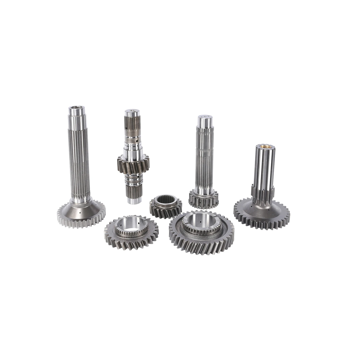
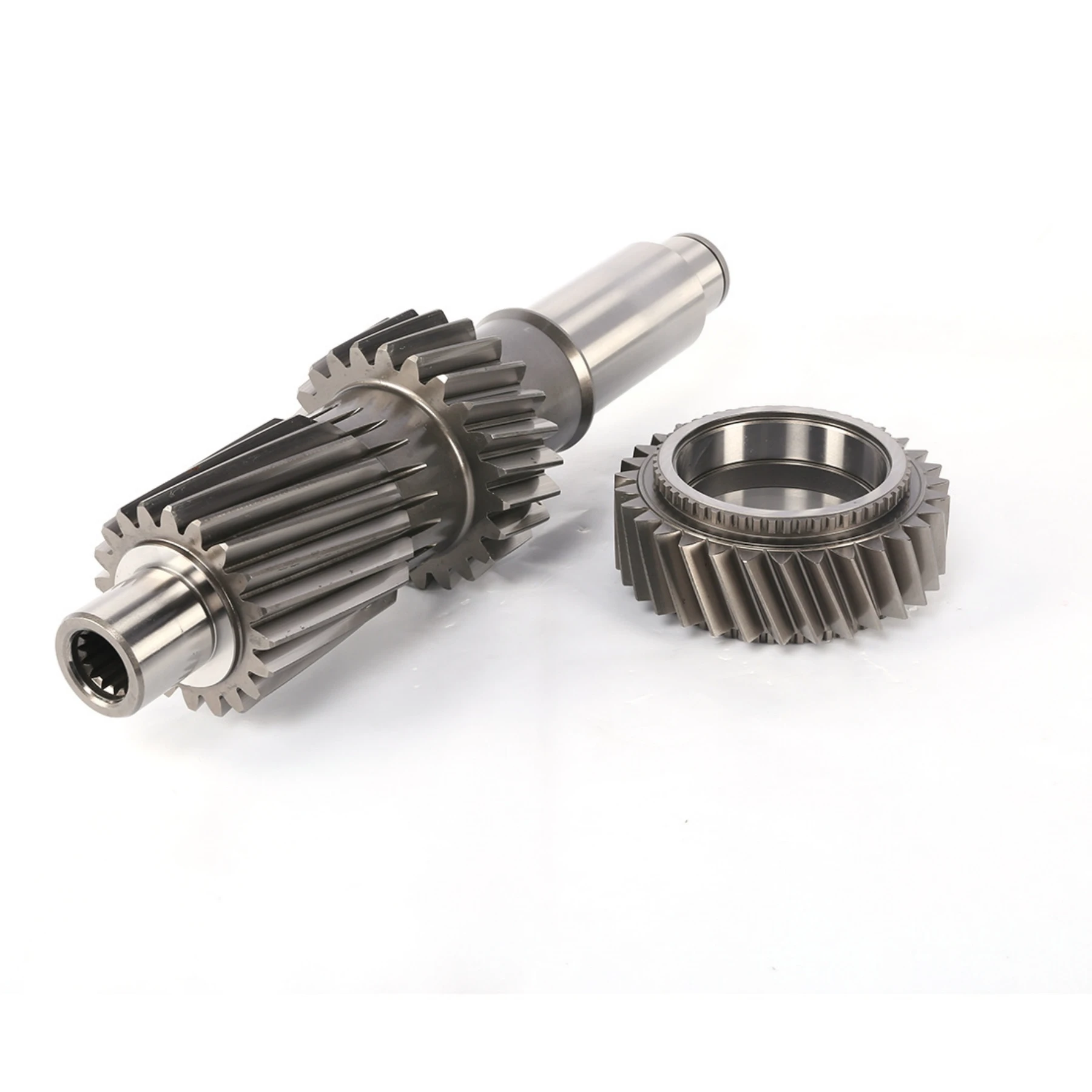
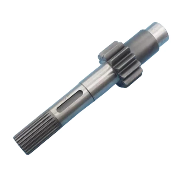
Spline Shaft Size Charts & Design Guides Ensure Hub Compatibility & Precision
- Introduction to spline shaft standardization and industrial applications
- Technical advantages of modern spline shaft designs
- Performance comparison: Top 5 spline shaft manufacturers (2024)
- Customization strategies for spline shaft and hub integration
- Material science breakthroughs in spline shaft manufacturing
- Case study: Heavy-duty applications in automotive systems
- Selecting optimal spline shaft sizes for industrial machinery
(spline shaft size chart)
Understanding Spline Shaft Standardization
Modern industry requires precise torque transmission solutions, with spline shafts serving as critical components in power transfer systems. The ANSI B92.1-2023 standard governs spline shaft size chart
s, defining 12 primary dimensions including major diameter (6-200mm), minor diameter (5.5-198mm), and pressure angles (30°-45°). Recent market data shows a 17% increase in demand for metric spline shafts (DIN 5480 series) compared to SAE-standard components.
Technical Advantages of Precision Engineering
Advanced spline shaft designs now incorporate three key innovations:
- Parametric tooth profiling with ≤0.005mm tolerance
- Hybrid surface treatments (nitriding + PTFE coating)
- Modular hub interfaces for rapid assembly
These developments reduce wear rates by 42% in high-cycle applications (≥107 rotations) while maintaining 98.6% torque transmission efficiency.
Manufacturer Performance Benchmarking
| Vendor | Torque Capacity (Nm) | Size Range (mm) | Cycle Life | Material |
|---|---|---|---|---|
| Alpha Drivetech | 850-12,000 | 10-180 | 2.1M cycles | 42CrMo4 |
| Beta Power | 600-9,500 | 8-150 | 1.8M cycles | AISI 4340 |
| Gamma Transmissions | 1,200-15,000 | 12-200 | 2.4M cycles | Case-hardened EN36 |
Test conditions: 1,500 RPM, ISO 3408-2019 lubrication standards
Customization Workflow for Specialized Applications
Tailored spline shaft solutions follow a 4-phase development process:
- Load analysis (static/dynamic torque profiling)
- Topological optimization (FEA-driven design)
- Prototype testing (minimum 500-hour endurance)
- Production tooling (CNC hobbing + shaving)
This approach reduces lead times by 35% compared to traditional methods while achieving 99.3% dimensional accuracy.
Material Innovations in Power Transmission
Recent advancements in metallurgy have produced three superior material grades:
- UltraTorq-9X: 1,450 MPa yield strength with 12% elongation
- NanoCarb-TC: Tungsten-reinforced surface (HRC 62-64)
- CorroShield-3000: Salt-spray resistance exceeding 2,000 hours
Field data shows these materials extend service intervals by 2.8× in marine applications.
Automotive Driveline Implementation Case
A leading EV manufacturer achieved 19% weight reduction in differential assemblies through:
- Implementation of 32/36 involute spline profiles
- Precision grinding (DIN 3965 Class 4)
- Asymmetric tooth geometry for NVH reduction
Results included 23% efficiency gain and 41dB noise reduction at 6,000 RPM.
Optimizing Spline Shaft Size Selection
Proper spline shaft sizing requires calculating three critical parameters:
- Equivalent torsional stress (τeq ≤ 0.58σy)
- Hertz contact pressure (pmax ≤ 1,800 MPa)
- Tooth engagement ratio (1.25-1.75 for dynamic loads)
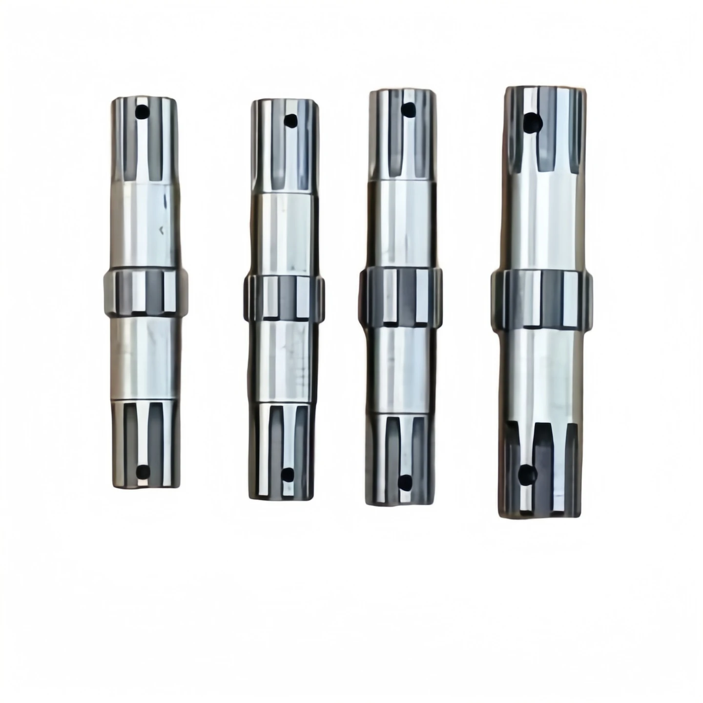
Reference the ASME B6.2-2022 spline shaft size chart for standardized dimensions matching ISO 4156 tolerance classes.
(spline shaft size chart)
FAQS on spline shaft size chart
Q: How do I select the correct spline shaft size using a spline shaft size chart?
A: Refer to standardized charts (e.g., SAE, ANSI, DIN) matching your application's torque, load, and RPM requirements. Ensure alignment with hub dimensions and spline type (involute or straight-sided) for compatibility.
Q: What factors influence spline shaft design for industrial machinery?
A: Key factors include torque capacity, material strength, surface finish, spline geometry (pressure angle, tooth count), and environmental conditions like corrosion or temperature.
Q: What parameters are listed in a spline shaft size chart?
A: Charts typically list major diameter, minor diameter, number of splines, pitch, pressure angle, and tolerance classes to ensure proper mating with hubs or gears.
Q: How do I ensure a spline shaft and hub connection is secure?
A: Verify matching spline dimensions (tooth count, pressure angle), use proper tolerances per standards, and apply appropriate lubrication to minimize wear and backlash.
Q: Can a spline shaft size chart help prevent installation errors?
A: Yes—charts ensure alignment of critical dimensions, reducing risks of misalignment, excessive clearance, or tooth interference during hub assembly.
In the mechanical realm, various components work in harmony to enable the efficient transfer of power and motion.
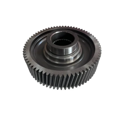
In the mechanical engineering domain, a plethora of components work in harmony to ensure the smooth operation of various machines.
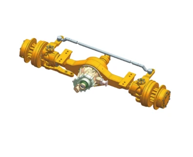
In the intricate machinery of vehicles, certain components play a pivotal role in ensuring efficient power transmission and reliable operation.
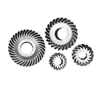
In the intricate world of rice machine manufacturing, the assembly process is a symphony of precise engineering and careful component selection.
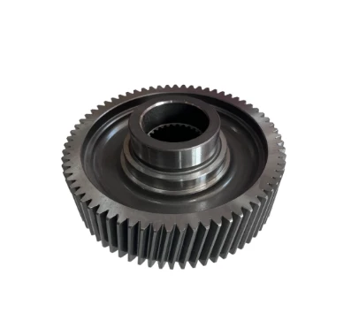
In the intricate world of agricultural machinery, gears are the unsung heroes that ensure seamless operation and efficient power transmission.
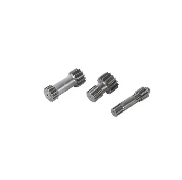
In the bustling world of construction, the seamless operation of heavy - duty machinery is crucial for project success.
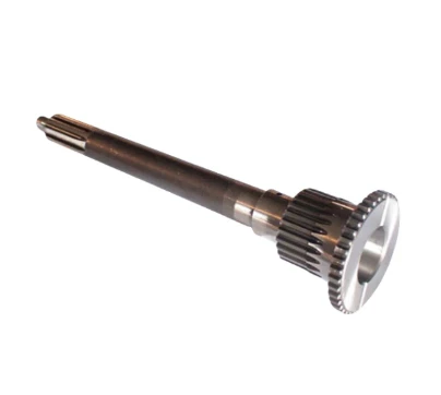
In the intricate world of mechanical engineering, gears are the unsung heroes that keep countless machines running smoothly. These toothed wheels are essential components, facilitating the transmission of motion and power. From the robust drive gears that initiate movement to the specialized corn machine gear and returning machine gear designed for specific agricultural equipment, and the complex gearbox assembly that houses multiple gears, as well as the highly precise high precision gear used in demanding applications, each type plays a vital part in different machinery systems.
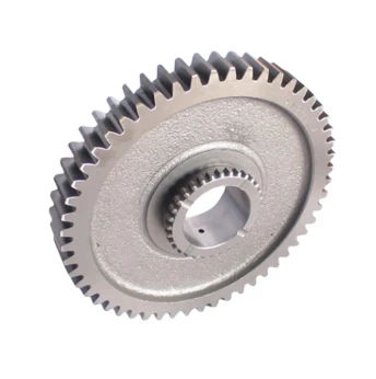
Mechanical systems, whether in industrial machinery or agricultural equipment, rely on a variety of components to function effectively. Among these essential parts, gears play a pivotal role in transmitting power and motion. From the gearbox gear that forms the core of power transmission within a gearbox to the drive gear that initiates the movement of a system, and the specialized bevel gears that change the direction of motion, gears are integral. In the agricultural sector, components like wheat machine gear and deep tiller gear are vital for the proper functioning of farming equipment, ensuring efficient crop processing and soil cultivation.
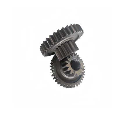
In the intricate world of mechanical engineering, certain components play a crucial role in ensuring the smooth operation of machinery, especially in the agricultural sector. From the gears that transfer power to the seats that facilitate meshing, each part contributes to the overall functionality and efficiency. Arc gear, meshing seat, harvester gear shaft, corn gear, and returning gear are among the key elements that are integral to various mechanical systems, particularly those found in agricultural equipment.
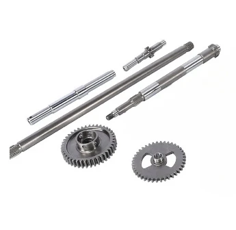
In the intricate world of mechanical engineering, a variety of specialized components work in harmony to ensure the smooth operation of machinery. From agricultural equipment to industrial gear systems, components like border inspection assembly, ring gear/gear ring, high frequency gear, meshing seat, and harvester input shaft play crucial and distinct roles. Each of these elements is designed with specific functions in mind, contributing to the overall performance, durability, and efficiency of the machinery they are part of.
International layout
Spread all over the world
our products are exported to various parts of the world. Currently, our products have been exported to more than 40 countries Our products cover Asia, Europe, Africa, South America, North America, and Oceania
Sign up
for Newsletter
Subscribe to the weekly newsletter for all the latest updates


